Antenna theory and practice
Picking the right antenna
For a roof or attic antenna
In the typical case, use a regular, omnidirectional antenna. The longest the antenna is, the better the gain, and gain improves transmission power, essentially.
For a remote node, far from most other nodes, a directional antennas is best: aim it at the nearest node nearby. It improves gain in one direction and reject noise from other directions. Either:
- A Yagi (better for outdoors)
- A panel (probably simpler for indoors, you can hang it from the ceiling in any orientation from two strings going to the top corners to orient it correctly)
For a window
In general, just use small antenna that came with your hardware.
If the building is large enough, you may get better results with a flat panel1 in the window, as it would reject noise from other devices in the back where you probably can't hear anything interesting through the building anyway, and improve contact with nodes on the window side.
In any case, for smaller setups, it's all a matter of having the best impedance match, which can be tested with a device called a Vector Network Analyzer, like the NanoVNA, essentially an antenna tester.
Longer cables will yield more power loss and lesser transmissions as well.
Theory and testing
Abstract
This is a rather theoretical section about antenna design. You probably don't need to know about this: just use the antenna that ships with your device or buy a more powerful antenna from the recommended list and you'll be fine.
Note that there is an antenna is "tuned" to a specific frequency, or more precisely to the "wavelength" of the frequency, which is an inverse function of the frequency. So any antenna is tuned to a specific wavelength, typically half or a quarter of the wavelength.
To compute the wavelength of a frequency, you take the speed of light:
c = 299 792 458 m/s
... and divide it by the frequency in Hertz, in our case about 900MHz:
c/915MHz = c/915 000 000 Hz ≈ 0.327 642 m ≈ 32.8 cm
So a correctly sized 915MHz antenna is about 33cm long. Note that 900MHz is relatively similar, about 4 mm longer:
c/900MHz ≈ 33.3 cm
For all intents and purposes, we often consider an antenna tuned for the middle of the frequency to be correct enough.
But all those stub antennas are not 30cm long, are they? That's because you can have antennas that are only a fraction of the wavelength, typically a half or quarter of the length, which makes antennas that are 16 cm or 8 cm long.
You can also have longer antennas. This blog post explains collinear antennas, which are omnidirectional antennas that are physically longer than the wavelength of the frequency we operate on, which improves the gain as well.
See also this guide that shows tests on various antennas to get a better idea on how to test antennas.
NanoVNA crash course
As mentioned above, a good antenna tester is the NanoVNA which you can order from Nooelec. Make sure you get a kit that covers the 915MHz range, which is not necessarily the case: some kits stop at 900MHz! Also get a closed case, some are more "bare boards" types of things. This link should be fine.
To test an antenna, it needs to be a SMA antenna. But lots of LoRa antennas are actually RP-SMA, so you will need a RP-SMA female to SMA male adapter which Nooelec oddly doesn't sell individually, but they do have a good connector kit which is useful to connect other random stuff you might get your hands on.
When you plug in the antenna, you will likely see one or a couple of "dips" in the yellow line: those are where the antenna is "tuned", where it will transmit better. By moving the cursor (with the little button) you can see which frequency those are.
If you are a radio wizard, you can also read the Smith chart in green to figure out the SWR (which you generally want to be below 2). But if, like me, you barely understand all of this, you might want to change one of the traces (say the cyan one) by going into "Display" and set it to "SWR".
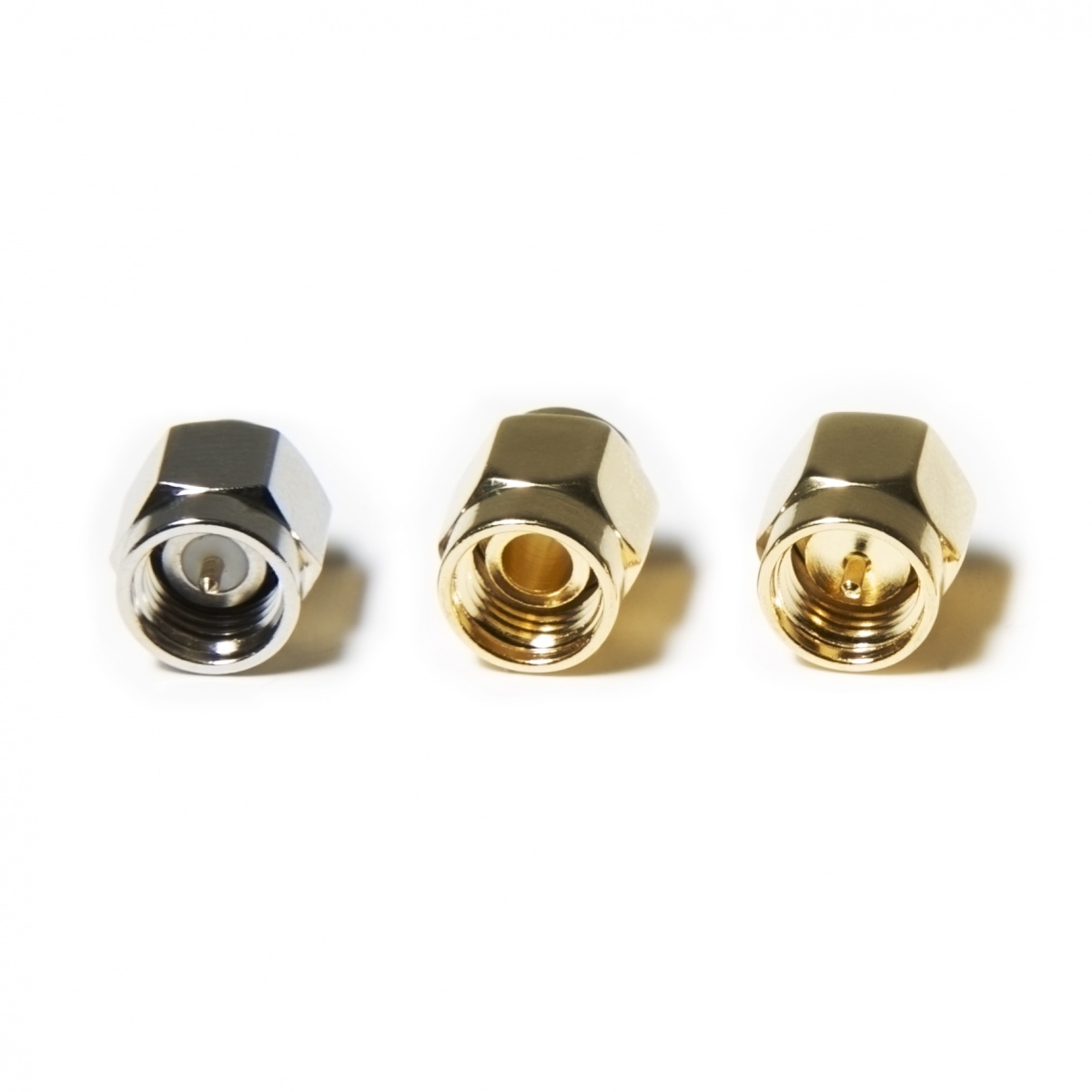
Typically, you also want to calibrate the device before doing any test beyond a quick checkup. For this, the NanoVNA normally ships with three little adapters that look like this image from Nooelec. Two have little conductor pins sticking out in the middle, one doesn't, one has a longer stub, and one is gray. The calibration guide will tell you to connect those in order: "OPEN", "SHORT", and "LOAD" or sometimes called "LONG". This is how you identify those:
-
"OPEN": the one without a pin, think "open electric circuit", because the pin doesn't connect because it's not there!
-
"SHORT": with a pin, short stub, same color (golden) as the "OPEN"
-
"LOAD": with a pin, longest stub, different color (gray, stainless)
You connect those in order and hit the "calibrate" menus in order. Yes, this is annoying, and yes, it's often necessary, otherwise you'll get inaccurate or useless results.
There's also this older website, the V2 Plus 4 manual (PDF).
-
Unfortunately there doesn't seem to be many affordable low gain panels on the market (such panels are typically sold as sector antennas, but not always flat). A normal flat panel like the ARC-PD0913C01 has 13 dBi of gain and a half power beam width of 38 degrees which isn't ideal for this application. Still, to perform worse than a <3dBi small antennas, you'd need to be at least than 1/8 power beam width, which is probably around 150 degrees. So worth a try. ↩